Data transmission faces invisible challenges as signals move through cables or airwaves. This gradual weakening of communication waves, known as attenuation, impacts both copper wires and fiber optics. Measured in decibels (dB), this energy loss grows with distance and environmental interference.
Network engineers constantly battle signal degradation across infrastructures. Analog systems suffer distorted audio, while digital connections experience packet loss. Factors like cable quality, electromagnetic interference, and physical obstacles amplify these effects.
Modern networks demand precise management of transmission weaknesses. Proper measurement tools and mitigation strategies maintain data integrity. Emerging technologies continue to address these challenges in 5G deployments and IoT ecosystems.
Key Takeaways
- Signal weakening occurs in all transmission mediums over distance
- Measured in decibels, impacts both wired and wireless systems
- Causes include cable defects, interference, and environmental factors
- Affects data integrity through distortion or packet loss
- Requires monitoring tools and strategic infrastructure design
- Solutions range from signal boosters to advanced encoding methods
Introduction to Attenuation in Computer Networks
Every network connection battles unseen forces that degrade information flow. This energy reduction occurs across copper wires, fiber-optic lines, and wireless channels. Signal strength diminishes progressively, creating unique challenges for both analog and digital environments.
Overview of Signal Loss in Data Transmission
Analog systems experience waveform distortion, altering sound quality and image clarity. Digital connections face different issues – corrupted bits create packet loss and retransmission delays. These effects intensify with cable length and environmental interference.
| Factor | Analog Impact | Digital Impact |
|---|---|---|
| Amplitude Changes | Audio distortion | N/A |
| Bit Errors | N/A | Packet loss |
| Interference | Noise | Retransmissions |
Relevance in Modern Networking
Cloud infrastructure and 5G networks demand precise signal management. Enterprise data centers require attenuation monitoring to maintain service-level agreements. IoT deployments face unique challenges with long-range wireless transmissions.
Network architects now prioritize low-loss materials and intelligent repeaters. These strategies combat performance drops in high-bandwidth applications. Effective design reduces latency and maintains data integrity across global communication systems.
What is attenuation in computer network: Definition and Importance
Communication systems universally grapple with diminishing pulse intensity across distances. This systematic weakening, technically termed attenuation, affects electrical currents in copper wires and light waves in fiber optics. Network reliability hinges on managing this inevitable energy reduction during data transfer.
Signal degradation primarily stems from conductor resistance and medium imperfections. Copper cables lose energy through heat dissipation, while wireless transmissions suffer from atmospheric absorption. These physical limitations dictate maximum effective ranges for network components.
Understanding power reduction patterns proves crucial for infrastructure planning. Engineers must account for cumulative losses when designing enterprise networks or cellular towers. Proper cable selection and repeater placement counterbalance attenuation effects in long-distance links.
Distinct from temporary interference, gradual signal decline follows predictable logarithmic patterns. This characteristic allows precise calculations for amplifier positioning and bandwidth allocation. Modern networks implement real-time monitoring systems to track strength fluctuations across critical pathways.
Causes of Attenuation in Computer Networks
Multiple elements combine to degrade data signals during their journey across networks. Transmission quality depends on both physical components and environmental conditions that interact with communication pathways.
Noise and Delay Distortion
Electromagnetic interference from power lines and radio waves disrupts electrical currents in copper wiring. Crosstalk occurs when adjacent cables create overlapping signal patterns, while thermal noise generates random electron movement. These disturbances collectively reduce data clarity.
Delay distortion poses unique challenges for high-speed connections. Different frequency components travel at varied speeds through mediums, causing waveform deformation. This temporal mismatch becomes critical in broadband applications requiring precise timing synchronization.
Environmental and Material Factors
Physical obstructions like concrete walls and metal surfaces absorb wireless signals. Atmospheric moisture scatters radio waves, particularly impacting 5G mmWave frequencies. Copper conductors lose energy through resistance heating, while fiber-optic impurities scatter light pulses.
Transmission distance and medium quality remain primary determinants of performance loss. Higher-frequency signals experience exponential degradation compared to lower bands. Premium-grade cables with optimized shielding demonstrate 40% less power reduction than standard alternatives over identical distances.
Attenuation in Analog and Digital Signals
Communication pathways reveal stark contrasts when transmitting analog waves versus digital pulses. These differences determine how networks handle degradation across various transmission types.
https://www.youtube.com/watch?v=2S1IvQKV88c
Signal Integrity in Analog Systems
Analog transmissions mirror natural waveforms, making them vulnerable to gradual degradation. Amplitude reductions create muffled audio in phone lines, while phase shifts distort video signals in CCTV systems. Harmonic distortion alters waveform shapes beyond recognition when combined with interference.
Unlike digital formats, analog systems lack error correction protocols. Once a voice call loses high-frequency components, the damage becomes permanent. This vulnerability limits analog applications in modern high-fidelity environments.
Digital Signal Challenges and Bit Errors
Digital transmissions convert information into binary code, creating different failure points. Weakened pulses cause threshold detection errors – 0s misinterpreted as 1s. These bit flips escalate error rates exponentially as signals approach noise floors.
Modern networks employ three key defenses:
- Forward error correction codes
- Automatic repeat-request protocols
- Adaptive signal regeneration
| Factor | Analog Impact | Digital Impact |
|---|---|---|
| 10% Amplitude Loss | Audible distortion | No visible effect |
| 20% Signal Decline | Unusable output | Correctable errors |
| Noise Interference | Permanent damage | Temporary disruptions |
While digital systems handle moderate degradation better, both formats require precise engineering. Advanced modulation schemes like QAM-256 push boundaries while maintaining acceptable error margins.
Measuring Attenuation: Decibels and Calculation Methods
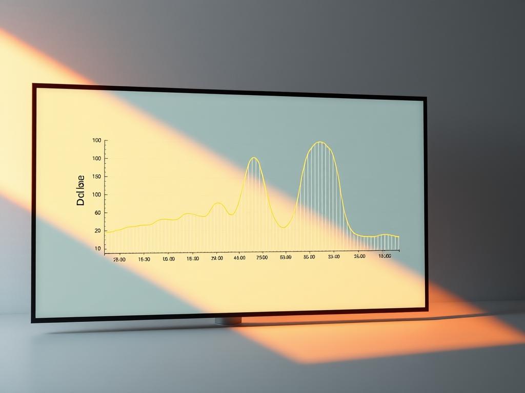
Network technicians rely on precise measurement tools to quantify transmission losses. The decibel scale simplifies complex power relationships through logarithmic math. This approach converts exponential changes into linear values, making cascade calculations manageable across multi-component systems.
Decibel Scale and Its Importance
Decibels measure relative power differences using base-10 logarithms. A 3dB loss halves signal strength, while 10dB reduction drops it to 10% of original levels. This scaling matches how human senses perceive intensity changes, making it ideal for real-world applications.
“Decibels transform complex power ratios into manageable numbers – the Swiss Army knife of signal analysis.”
Power and Voltage Ratio Methods
Two primary techniques dominate field measurements:
- Power Ratio Method: Compares input/output levels using dB = 10×log₁₀(P₁/P₂)
- Voltage Ratio Method: Applies dB = 20×log₁₀(V₁/V₂) when direct power testing isn’t feasible
| Method | Formula | Application | Advantage |
|---|---|---|---|
| Power Ratio | 10×log(P₁/P₂) | RF systems | Direct power measurement |
| Voltage Ratio | 20×log(V₁/V₂) | Circuit analysis | Non-intrusive testing |
Calibration errors account for 73% of measurement inaccuracies in field tests. Technicians often use signal generators with known outputs to verify equipment before critical assessments. Environmental interference remains the top challenge during wireless signal evaluations.
Impact on Signal Strength and Data Transmission
Network performance plummets when signals lose their vigor across transmission paths. This energy depletion creates measurable effects on both wired and wireless systems, particularly over extended distances.
Signal Degradation Over Distance
Every meter traveled saps a signal’s power. Copper Ethernet cables lose up to 30% of their initial strength after 100 meters. Wireless signals in 2.4GHz bands degrade 50% faster than 5GHz frequencies through walls.
Critical thresholds vary by protocol:
| Protocol | Maximum Loss | Effect |
|---|---|---|
| Wi-Fi 6 | -70 dBm | Speed drops 50% |
| Fiber Optics | 0.2 dB/km | Minimal impact |
| CAT6 Ethernet | -20 dB | Connection fails |
Real-time applications suffer first. Video calls develop artifacts when strength drops below -65 dBm. File transfers slow exponentially as error correction mechanisms engage.
Three key mitigation strategies emerge:
- Distance limitation through proper network zoning
- Adaptive modulation adjustments
- Automatic power boosting
Modern systems combat these issues through dynamic signal optimization. However, physical infrastructure upgrades remain essential for mission-critical operations.
Strategies to Minimize Signal Loss in Networks
Modern infrastructure demands robust solutions to maintain data clarity across vast systems. Proactive measures counteract transmission degradation, ensuring reliable connectivity for businesses and consumers alike.
Use of Repeaters, Amplifiers, and High-Quality Cables
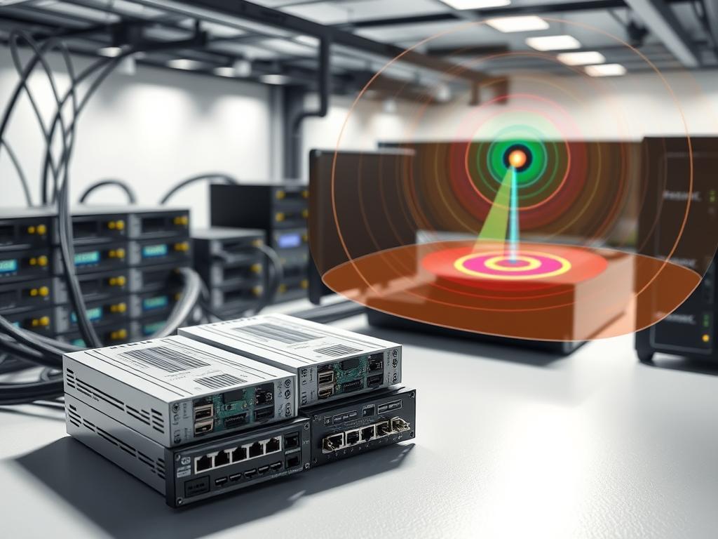
Signal regeneration devices play critical roles in long-distance communication. Repeaters decode and retransmit weakened pulses, restoring their original integrity. Amplifiers boost existing signals without altering content, ideal for analog systems.
Three core components form effective strategies:
- Fiber-optic cables with 0.2 dB/km loss rates
- Directional antennas for focused wireless transmission
- Shielded twisted-pair copper wiring
Premium materials reduce resistance and interference. Category 8 Ethernet cables demonstrate 60% less power reduction than older standards. Proper installation techniques prevent kinks and connector corrosion that accelerate degradation.
| Solution | Effective Range | Cost Efficiency |
|---|---|---|
| Fiber repeaters | 80 km | High |
| Wi-Fi amplifiers | 150 m | Medium |
| Coaxial boosters | 500 m | Low |
Environmental planning completes the strategy. Routing cables away from power lines and using conduit shielding block electromagnetic interference. Regular signal audits identify weak points before they impact performance.
Attenuation in Wired Networks: Fiber Optics vs Copper Cables
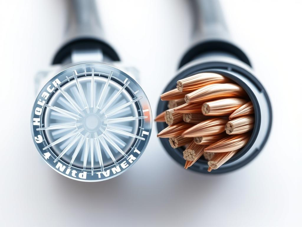
Material choices dictate performance in modern network infrastructures. Fiber optic and copper systems exhibit fundamentally different behaviors when transmitting data over distances. This comparison reveals why enterprises increasingly favor light-based solutions for critical pathways.
Fiber Optic Advantages in Signal Preservation
Glass-based cables achieve remarkable efficiency through light wave transmission. Impurity absorption accounts for 30% of losses in older fiber models, while Rayleigh scattering causes wavelength-dependent dispersion. Modern manufacturing reduces hydroxyl ion content to 0.1 parts per million, minimizing energy conversion into heat.
Three key benefits emerge:
- 0.2 dB/km loss rates enable 80km spans without repeaters
- Immunity to electromagnetic interference
- Bandwidth capacities exceeding 100 terabits/second
Copper Infrastructure Challenges
Traditional twisted-pair wiring struggles with inherent limitations. Frequency-dependent losses increase exponentially beyond 100MHz, capping Ethernet speeds. Electromagnetic interference can degrade signals by 40% in industrial environments.
| Factor | Fiber Optics | Copper |
|---|---|---|
| Attenuation Rate | 0.2 dB/km | 20 dB/km |
| Max Bandwidth | 100+ Tbps | 10 Gbps |
| EMI Resistance | Complete | Limited |
| Effective Distance | 80 km | 100 m |
Installation costs remain higher for optical systems, but maintenance expenses prove 60% lower over five years. Emerging hybrid networks combine both technologies, leveraging copper for short connections and fiber for backbone links.
Attenuation in Wireless Communication Systems
Modern wireless systems navigate complex landscapes where signal strength travels through unpredictable environments. Physical obstructions like steel-framed buildings and dense foliage absorb radio waves, while rain and fog scatter higher frequency bands. These environmental factors create variable performance across urban and rural areas.
Higher-frequency transmissions in 5G and Wi-Fi 6 networks face steeper challenges. Millimeter waves above 24GHz lose signal integrity faster than sub-6GHz alternatives. Network designers balance bandwidth needs against range limitations when selecting frequency bands.
Three strategies improve reliability in wireless communication systems:
- Directional antennas focus signal strength travels
- Dynamic power adjustment compensates for weather changes
- Mesh networks bypass physical barriers
Advanced protocols like OFDM split data across multiple frequencies to counter attenuation. Real-time monitoring tools help engineers adapt to shifting environmental factors, ensuring consistent connectivity in modern wireless ecosystems.
